
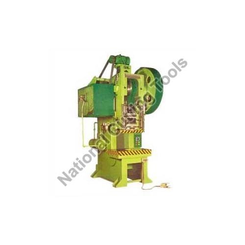
Tooling setup, die clearance calculations, flywheel energy balancing, and tonnage sizing for stamping scaffolding base plates and top cups on C-frame mechanical power presses.
Every commercial scaffolding manufacturing facility requires high-speed mechanical power presses to blank, pierce, form, and emboss auxiliary components. Scaffolding base plates (150 mm x 150 mm x 6 mm), sole plates, top cups, prop pin holes, and ledger end blanking are all processed on mechanical punch presses.
Operating a mechanical press efficiently requires an exact understanding of cutting tonnage calculations, proper die clearance to prevent tool chipping, and flywheel energy maintenance during continuous stamping cycles.
Punching Tonnage Calculation for Mild Steel Base Plates
Underestimating press tonnage results in frame deflection, premature crankshaft bushing failure, and cracked dies. The cutting force required to punch holes and blank plate edges is calculated using the standard shear formula:
Punching Force (Tons) = [Perimeter of Cut (mm) x Plate Thickness (mm) x Shear Strength (kg/mm2)] / 1000
For a standard scaffolding base plate:
- Plate thickness: 6 mm mild steel (Shear strength approx 40 kg/mm2).
- Four corner nail holes (14 mm diameter) plus one center spigot hole (38 mm diameter): Total perimeter = 295 mm.
- Calculated piercing force: (295 x 6 x 40) / 1000 = 70.8 Tons.
Die Clearance Standards for Burr-Free Stampings
Improper clearance between punch and die causes excessive burr formation or extreme punch load:
- For Mild Steel (IS 2062): Total radial clearance should equal 7% to 9% of plate thickness. For 6 mm plate, total die clearance is 0.48 mm to 0.54 mm.
- Die Material: Punches and die inserts should be machined from D2 or D3 high-carbon high-chromium alloy steel vacuum hardened to 58-60 HRC.
Heavy-Duty Frame Architecture & Crankshaft Bushings
National Cutting Tools builds power press side frames from solid, ultrasonically tested steel plates, fully stress-relieved prior to machining. The forged EN9 crankshaft rotates inside precision-bored phosphorus bronze bushings with positive centralized oil lubrication, ensuring zero angular deflection even during maximum tonnage punching.
Contact our Ludhiana engineering team at +91-9888210800 to discuss die tooling sets, mechanical feeder attachments, and press specifications.
Senior Machine Tool Design & Production Engineering Division, Ludhiana Works
Authored by machine tool builders at our Ludhiana manufacturing works. Every technical parameter, metallurgy guideline, electrical formula, and production cycle stated in this guide is reviewed by our shop-floor engineers who assemble, wire, and execute material trials before global dispatch to GCC and domestic manufacturing facilities.
Need Engineering Consultation on This Subject?
Speak directly with National Cutting Tools senior machinery engineers.