
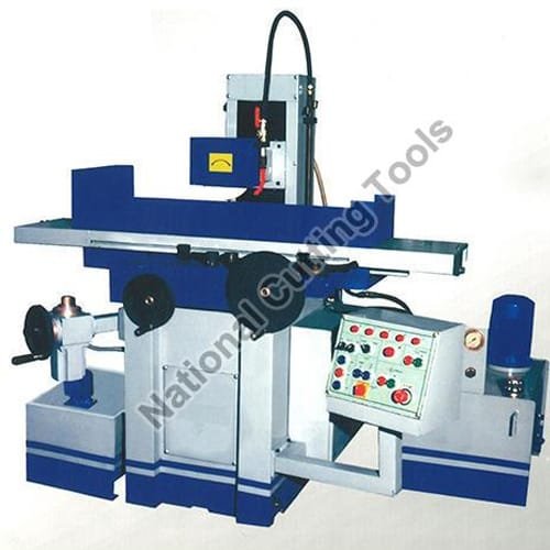
A practical engineering guide comparing hydraulic surface grinders, universal cylindrical grinding machines, and toolroom sharpeners. Covers wheel grade selection, magnetic chuck holding forces, hydraulic oil viscosity, and micron-level runout tolerances.
Precision Surface and Cylindrical Grinding in Industrial Manufacturing
In precision manufacturing, turning and milling bring components close to dimension, but grinding delivers the critical final tolerance, concentricity, and surface finish (Ra values below 0.4 µm). For toolrooms, die and mould shops, hydraulic cylinder manufacturers, and machine tool builders, selecting between a hydraulic surface grinder and a universal cylindrical grinding machine determines throughput, component rejection rates, and long-term repeatability.
At National Cutting Tools in Ludhiana, our machine tool division builds both horizontal-spindle reciprocating surface grinders and universal cylindrical grinders. This guide breaks down the core engineering criteria required to specify the right machine for your workshop operations.
1. Surface Grinding vs Cylindrical Grinding: Core Geometry
The choice between surface and cylindrical grinding depends on workpiece geometry and alignment requirements:
- Horizontal Spindle Surface Grinders: Feature a reciprocating rectangular magnetic chuck or rotary table. The periphery of a vitreous-bonded grinding wheel cuts flat surfaces, datum faces, slide guideways, shear blades, and press die bolster plates. Our hydraulic models deliver stroke lengths from 450 mm to 1500 mm.
- External & Universal Cylindrical Grinders: Hold workpieces between dead centers or in a precision 3-jaw/4-jaw chuck. The wheelhead advances into a rotating round part to finish outer diameters (OD), stepped motor shafts, bearing seatings, hydraulic piston rods, and inner diameters (ID) using an internal grinding spindle attachment.
2. Spindle Construction & Bearing Tolerances (DIN 8606 Standard)
The heart of any industrial grinder is the wheelhead spindle. Commercial fabricators frequently make the error of using standard radial ball bearings, which fail under heavy grinding thrust and develop chatter marks on the workpiece.
Industrial grinders manufactured at our works feature:
- Forged EN-31 alloy steel main spindles, vacuum-hardened and ground to sub-micron accuracy.
- Matched pairs of super-precision angular contact bearings (SKF or FAG P4/ABEC-7 class) preloaded to absorb both axial grinding thrust and radial deflection.
- Total spindle nose radial runout strictly held under 0.002 mm to 0.003 mm.
- Dynamic balancing of the complete wheel flange assembly before testing to eliminate micro-vibrations that cause faceted surface finishes.
3. Hydraulic Circuit Design & Thermal Stability
In reciprocating surface grinders, smooth table reversal without shock is vital. Harsh reversals cause table float and uneven depth of cut at stroke ends. Our machines utilize variable-displacement hydraulic pump stations isolated from the main cast bed to prevent heat transfer from hydraulic oil to the machine frame.
We recommend ISO VG 32 or ISO VG 46 anti-wear hydraulic oil maintained between 35°C and 45°C. The bed guideways are lined with Turcite-B anti-friction sliding material and supplied with continuous metered centralized lubrication to prevent stick-slip motion at low feed speeds.
4. Grinding Wheel Selection: Abrasive and Grit Matrix
| Material to Grind | Abrasive Type | Grit Size | Wheel Grade | Bond Type |
|---|---|---|---|---|
| Mild Steel / IS 2062 | Aluminium Oxide (White / Brown) | 46 – 60 | H / I / J | Vitrified (V) |
| Tool Steels (D2, D3, H13) Hardened | White Aluminium Oxide / Ceramic | 60 – 80 | G / H | Vitrified (V) |
| Cast Iron / Non-Ferrous | Silicon Carbide (Green) | 36 – 46 | I / J / K | Vitrified (V) |
| Tungsten Carbide Tool Tips | Diamond (PCD) / CBN | 120 – 200 | Medium | Resinoid / Metal |
5. Factory Inspection & Sizing Checklist
When selecting a machine from our grinding machinery division, review these 4 practical parameters:
- Maximum Table Working Capacity: Measure the diagonal dimension of your largest die block plus clamping allowance. For general toolrooms, a 200 mm × 450 mm or 300 mm × 600 mm chuck handles 85% of standard tooling.
- Height Under Wheel: Check clearance from the top of the magnetic chuck to the bottom of a new grinding wheel. Ensure adequate daylight for tall work fixtures or angle sine vices.
- Magnetic Chuck Type: Permanent magnetic chucks suffice for flat steel plates up to 400 mm; electro-magnetic chucks with automatic demagnetizing controllers are mandatory for large plate grinding to prevent component distortion upon release.
- Dust Extraction & Wet Coolant System: High-volume coolant delivery with a magnetic paper band separator prevents fine metallic swarf from recirculating through the coolant nozzle and scratching finished surfaces.
For custom bed lengths, high-precision cylindrical tooling, or export inquiries, contact our machine building engineering team in Ludhiana.
Machines covered in this guide
Senior Machine Tool Design & Production Engineering Division, Ludhiana Works
Authored by machine tool builders at our Ludhiana manufacturing works. Every technical parameter, metallurgy guideline, electrical formula, and production cycle stated in this guide is reviewed by our shop-floor engineers who assemble, wire, and execute material trials before global dispatch to GCC and domestic manufacturing facilities.
Need Engineering Consultation on This Subject?
Speak directly with National Cutting Tools senior machinery engineers.