
Tonnage, frame type, stroke, shut height and die space decide whether a press suits your component. A practical selection guide for fabricators buying a mechanical or hydraulic press.
A press is bought once and lived with for twenty years. Most of the disappointment we hear about comes from two decisions made at the enquiry stage: a tonnage chosen from the component's thickness alone, and a frame chosen because it was the cheapest one that fit the budget. This guide sets out the numbers that actually decide whether a press will do your work.
Start with the component, not the machine
Before comparing machines, write down five things about the part you intend to produce:
- Material and grade, and whether it is hot rolled, cold rolled or stainless.
- Thickness, and the longest cut length in a single stroke.
- The operation: blanking, piercing, bending, deep drawing or coining.
- Parts required per shift, which sets the strokes per minute you need.
- Die size and shut height, including any feeder or stripper attached to it.
Those five lines determine tonnage, frame, stroke and bed size. Everything else is preference.
Working out the tonnage
For blanking and piercing, the force needed is the cut length multiplied by the material thickness multiplied by the shear strength of the material:
Force (tonnes) = perimeter cut (mm) × thickness (mm) × shear strength (kg/mm²) ÷ 1000
Shear strength is roughly 80 per cent of tensile strength. For mild steel it is commonly taken as 35–40 kg/mm², for stainless considerably higher. A 300 mm cut perimeter in 3 mm mild steel therefore needs in the region of 36 tonnes.
Two corrections matter in practice. Add a safety margin of about 30 per cent, because tooling wears, material varies batch to batch, and a press run at its limit is a press that breaks. And check the energy, not just the force: a mechanical press stores energy in a flywheel, and deep or long strokes drain it faster than the motor can restore. If your work is drawing rather than blanking, size on energy and consider a hydraulic press instead.
Where the force is available
Rated tonnage on a mechanical press is only available near the bottom of the stroke, typically the last 6 mm or so. A press rated 100 tonnes may deliver far less 30 mm above bottom dead centre. If your operation does work high in the stroke, such as a deep form, discuss the rated point with the manufacturer rather than reading the headline figure.
Choosing the frame
| Frame | Suits | Watch for |
|---|---|---|
| C frame (gap frame) | Blanking, piercing, light forming. Three-sided access makes loading and automation easy. | The C opens slightly under load, so tool alignment suffers at high tonnage and on long dies. |
| Pillar type (straight side) | Heavier tonnage, longer dies, progressive tooling, tighter tolerances. | Larger footprint and a higher price; access is from front and back only. |
| Friction screw press | Forging, upsetting, coining, hot work where a controlled blow is wanted. | Slower cycle; energy per blow is set by the flywheel and screw, not a fixed tonnage. |
| Hydraulic press | Deep drawing, straightening, pressing operations needing full force over a long stroke. | Slower strokes per minute than a mechanical press of the same tonnage. |
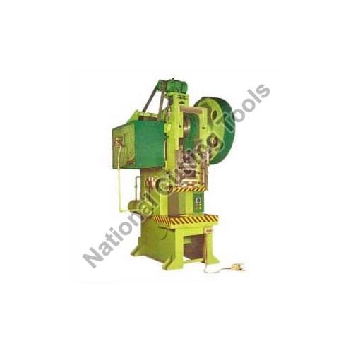
As a rule of thumb: if the die is longer than the gap will comfortably support, or the tolerance is tight enough that a few tenths of frame deflection matter, move to a pillar type press. For general blanking and piercing on scaffolding and sheet metal components, a C frame power press remains the practical choice.
Stroke, shut height and bed
Three dimensions decide whether your die physically fits and clears:
- Stroke length must clear the finished part plus the feed height. Deep parts need long strokes, which costs flywheel energy.
- Shut height is the distance between the ram face at bottom dead centre and the bolster. Your die's closed height must sit inside the adjustment range, with room left for a parallel or riser.
- Bed and bolster size must take the die plus the clamping. Leave space at the edges for T-slots and clamps.
Ask for these three figures in writing before ordering. They are the commonest cause of a press arriving and a die not fitting.
Strokes per minute and the real output
Rated strokes per minute is a machine figure, not a production figure. Actual output depends on how the blank is fed and the part removed. Hand feeding on a guarded press might achieve a quarter of the rated rate; a coil feed with air ejection approaches it. If output per shift is the reason for the purchase, discuss feeding at the same time as the press, not afterwards.
Safety and controls
Specify the safety arrangement with the machine rather than adding it later:
- Two-hand control on hand-fed work, with anti-tie-down and anti-repeat.
- Fixed guards where the die area does not need access, interlocked guards where it does.
- A clutch and brake capable of stopping the ram mid-stroke, and a brake monitor if light curtains are used.
- An emergency stop that drops power to the clutch, within reach of the operator position.
The electrical build must also match your supply. Machines going to the GCC and South East Asia are commonly wired for 380–415 V three phase at 50 or 60 Hz; tell the maker your voltage and frequency at the quotation stage so the motor and switchgear are ordered correctly.
Presses for scaffolding component work
Scaffolding fabricators generally need a press for bottom cups, top cups, base plates and pressed brackets. Cup pressing is a drawing operation, so it wants either a generously sized mechanical press or a hydraulic press; a double action deep drawing press holds the blank while the punch draws it, which controls wrinkling on deeper cups. Plate work such as base plates and fixing brackets is straightforward blanking and piercing, and sits comfortably on a C frame machine.
Questions worth asking any supplier
- At what point in the stroke is rated tonnage available?
- What is the shut height range, and the bolster size including usable T-slots?
- What is the flywheel energy per stroke, and the recommended maximum continuous rate?
- How is the clutch operated, and what is the stopping time?
- Will the machine be run off on my material before dispatch, and can I see that recorded?
Frequently asked questions
Mechanical or hydraulic press?
Mechanical presses are faster and better suited to blanking and piercing. Hydraulic presses deliver full force anywhere in the stroke, which suits drawing, straightening and pressing work, and they are easier on tooling in deep operations.
How much extra tonnage should I allow?
Around 30 per cent above the calculated requirement is usual. It covers tool wear, material variation and the occasional heavier job, and keeps the machine off its limit.
Can one press cover blanking and deep drawing?
It can, but it will do one of them poorly. If drawing is a significant part of the work, it is generally cheaper over the life of the plant to run a mechanical press for blanking and a hydraulic press for drawing than to compromise on a single machine.
If you send the component drawing, material and thickness, the output per shift you need and your supply voltage, our works in Ludhiana will come back with the tonnage, the frame we would recommend and the die space it offers. Browse the power press range or send the details to the export desk.
Machines covered in this guide
Senior Machine Tool Design & Production Engineering Division, Ludhiana Works
Authored by machine tool builders at our Ludhiana manufacturing works. Every technical parameter, metallurgy guideline, electrical formula, and production cycle stated in this guide is reviewed by our shop-floor engineers who assemble, wire, and execute material trials before global dispatch to GCC and domestic manufacturing facilities.
Need Engineering Consultation on This Subject?
Speak directly with National Cutting Tools senior machinery engineers.